Zener diode is a reverse-biased heavily doped silicon diode named after the invention by C.Zener. Zener diode is specially designed to operate in the breakdown region. The doping level of silicon diodes can be varied as per breakdown voltages needed from 2V to 1000 V.
The maximum reverse bias applied before entering into the Zener region is called the Peak Inverse Voltage. It is commercially referred to as PIV rating.
Zener diode symbol By ZyMOS – Own work, Public Domain, https://commons.wikimedia.org/w/index.php?curid=5617769
The process of converting alternating current into the direct current is called Rectification. There are two types of rectifiers, one is a half-wave rectifier and the other is a full-wave rectifier.
Half-wave Rectifier Circuit
The circuit consists of a transformer, a p-n junction diode, and a resistor. In a half-wave rectifier circuit, either a positive half or the negative half of the AC input is passed into while the other half is blocked.
Only one-half of the input wave reaches the output. Therefore, it is called a half-wave rectifier. Here p-n junction diode acts as a rectifying diode. The efficiency of the Half wave rectifier is 40.6%
Full Wave Rectifier
The positive and negative half cycles of the AC input signal pass through the full-wave rectifier circuit and are called a full-wave rectifier.
It consists of two p-n junction diodes, a centre tapped transformer, and a load resistor (RL). The efficiency of a full-wave rectifier is twice the half-wave rectifier which is 81.2%. It is due to positive and negative cycles being rectified.
There are two types of Semiconductors. They are Intrinsic and Extrinsic semiconductors.
Types of Semiconductors
Intrinsic Semiconductor
Extrinsic Semiconductor
Intrinsic Semiconductor
A semiconductor in its pure form without impurity is called an intrinsic semiconductor.
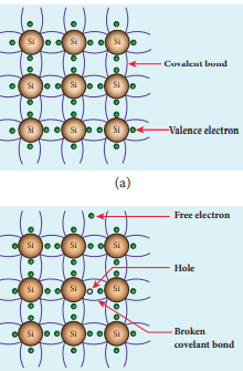
Here impurity means any other atom in the crystal lattice. Each Silicon atom has four electrons in the outermost orbit and is covalently bonded with the neighboring atoms to form the lattice.
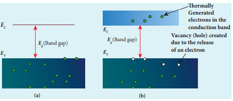
A small increase in temperature is sufficient enough to break some of the covalent bonds and release the electrons free from the lattice.
As a result, some states in the valence band become empty and the same number of states in the conduction band will be occupied. The vacancies produced in the valence band are called holes.
As the holes are deficient in electrons, they are treated to possess positive charges. Hence, electrons and holes are the two charge carriers in semiconductors. In intrinsic semiconductors, the number of electrons in the conduction band is equal to the number of holes in the valence band.
The conduction is due to the electrons in the conduction band and holes in the valence band.
These currents are represented as Ie and Ih respectively.
The total current (I) is always the sum of the electron current (Ie) and the hole current (Ih). I = Ie + Ih .
An intrinsic semiconductor behaves like an insulator at 0 K. The increase in temperature increases the number of charge carriers (electrons and holes).
The intrinsic carrier concentration is the number of electrons in the conduction band or the number of holes in the valence band in an intrinsic semiconductor.
Extrinsic Semiconductor
When a carrier concentration is not enough in an intrinsic semiconductor, some impurities are added to increase the carrier concentration. The process of adding impurities to the intrinsic semiconductor to increase the carrier concentration is called Doping.
The impurities atoms are called dopants and are of order 100 ppm. There are two types of extrinsic semiconductors one is an n-type semiconductor and another one is a p-type semiconductor.
Both n-type and p-type semiconductors are neutral as topping neutral atoms to the intrinsic semiconductor.
N-type Semiconductor
An n-type semiconductor is made of doping pure germanium or silicon with a dopant from group V pentavalent impurities (element, compound, or mixture) such as Phosphorus, Arsenic, and Antimony.
The majority carriers of current in an n-type semiconductor are electrons and the minority carriers are holes.
A semiconductor doped with a pentavalent impurity is called an n-type semiconductor.
P-Type Semiconductor
Germanium or Silicon substrate are doped with trivalent atoms from group-iii elements such as Boron, Aluminium, Gallium and indium.
An extrinsic semiconductor where the holes are the majority carriers and thermally generated electrons are minority carriers is called a P-type semiconductor.
The electrons present in the outermost shell of an atom are called Valence electrons.
From the Bohr-Bury scheme, we find the outermost shell of an atom can accommodate a maximum of 8 electrons.
Also, the atoms of the elements show little chemical activity if its outermost shell is completely filled. Also can be said that the elements combining capacity or its valency is zero.
In the inert elements, the helium atoms have two electrons in their outermost shell and all other elements have atoms with 8 electrons in the outermost shell.
The combining capacity of atoms of other elements to react or form molecules with atoms of the same or different elements were the attempts to attain a fully filled outmost shell.
An outermost shell that has 8 electrons is said to be octet.
The atoms would attempt or react to achieve an octet in the outermost shell and this process will be done by gaining, losing, or sharing the electrons.
The losing, gaining, or sharing of electrons gives the direct combining capacity of the elements.
Example Sodium/lithium/hydrogen atoms contain one electron each in its outermost shell so as to lose one electron. These elements are said to have a valency of One (1).
Similarly, the valency of Magnesium is 2, as it has 2 electrons in the outermost shell and aluminum is 3 as it has 3 electrons in the outermost shell.
Valency of Metals
Metals have positive valency as they have +1,+2,+3 electrons in their outermost or valance shell.
The metal having valency ‘1’ is potassium its chemical symbol is K . Potassium is an alkali metal and belongs to Group 1 of the periodic table.
In the vast theater of natural forces that shape our planet, one phenomenon stands both mysterious and indispensable – geomagnetism. The invisible dance of magnetic fields around the Earth has captivated scientists, explorers, and thinkers for centuries. In this blog post, we embark on a journey to unravel the intricacies of geomagnetism, exploring its origins, manifestations, and the profound impact it has on our world.
The Earth’s Magnetic Symphony:
At the heart of geomagnetism lies the Earth’s magnetic field, a dynamic force that envelops our planet like an invisible cocoon. Understanding the basics of this magnetic symphony, including the North and South Magnetic Poles, provides a foundation for comprehending the larger tapestry of geomagnetic phenomena.
Geomagnetic Components:
Geomagnetism expresses itself through three key components: declination, inclination, and intensity. Each of these elements contributes to the unique characteristics of Earth’s magnetic field, shaping its behavior across different regions and elevations.
Navigating by the Magnetic Compass:
The historical significance of geomagnetism in navigation cannot be overstated. From ancient mariners relying on lodestones to modern GPS systems, understanding the Earth’s magnetic field has been crucial for navigating vast oceans and uncharted territories. This section explores the evolution of navigation tools and the role geomagnetism plays in guiding explorers.
Magnetic Anomalies and Earth’s Interior:
Delving into the connection between geomagnetism and the Earth’s interior unveils a fascinating tale of molten iron, convective currents, and the geodynamo theory. Magnetic anomalies on the Earth’s surface provide clues about the composition and dynamics of the planet’s core, allowing scientists to peer into the depths of our world.
Geomagnetism and Climate Studies:
The interplay between geomagnetism and climate studies is a relatively unexplored frontier. Investigating how variations in the Earth’s magnetic field may influence climate patterns opens a new avenue for understanding the intricate connections between Earth’s spheres.
Auroras: Nature’s Magnificent Light Show:
One of the most visually stunning displays of geomagnetism occurs in the polar regions with the auroras. Exploring the connection between the solar wind, charged particles, and the Earth’s magnetic field unveils the science behind these celestial light shows.
Practical Applications and Modern Technology:
In our technologically driven world, geomagnetism continues to play a vital role. From compasses and navigation systems to the shielding of electronic devices from cosmic radiation, the practical applications of geomagnetic knowledge permeate various aspects of our daily lives.
Challenges and Future Frontiers:
As we navigate the complexities of geomagnetism, it’s essential to recognize the challenges scientists face in understanding this intricate forcefully. From predicting geomagnetic storms to exploring the potential impacts of a magnetic pole reversal, the future frontiers of geomagnetic research hold both promise and uncertainty.
Earth Magnetism
Some of the causes of earth magnetism are
Earth’s magnetism, a fundamental aspect of our planet’s geophysical properties, is a result of complex processes occurring deep within the Earth. Several factors contribute to the generation of Earth’s magnetic field, creating the phenomenon known as geomagnetism. Here are some of the key causes:
Geodynamo Effect:
The primary cause of Earth’s magnetism is attributed to the geodynamo effect. This process occurs in the outer core of the Earth, which is composed mainly of molten iron and nickel. The rotation of the Earth and the heat generated from the decay of radioactive isotopes within the core drive convective currents. These circulating molten metals generate electric currents through the motion of charged particles, ultimately producing a magnetic field.
Earth’s Rotation:
The rotation of the Earth on its axis plays a crucial role in the generation of its magnetic field. The movement of the molten iron in the outer core, coupled with the rotation of the Earth, induces the flow of electric currents, contributing to the creation of the geomagnetic field.
Convection Currents in the Outer Core:
Convection currents, driven by the heat escaping from the Earth’s interior, are responsible for the movement of molten iron and nickel in the outer core. These currents generate electric currents through the motion of charged particles, which, in turn, contribute to the formation and maintenance of the geomagnetic field.
Composition of the Core:
The composition of the Earth’s core, particularly the presence of iron and nickel, is crucial for the generation of its magnetic field. The motion of these metals in a liquid state, coupled with their ability to conduct electricity, facilitates the formation of the geomagnetic field.
Magnetic Minerals in Earth’s Crust:
While the primary source of Earth’s magnetic field lies in the outer core, certain magnetic minerals in the Earth’s crust also contribute to local variations in the magnetic field. Rocks containing magnetic minerals, such as magnetite, can influence the overall magnetic signature of a region.
Changes in the Earth’s Magnetic Field over Time:
Over geological time scales, the Earth’s magnetic field undergoes changes, including reversals of polarity where the magnetic north and south poles switch places. The reasons for these reversals are not fully understood, but they are believed to be linked to complex processes within the Earth’s core.
External Influences – Solar Wind:
The solar wind, a stream of charged particles emanating from the Sun, interacts with the Earth’s magnetic field. This interaction creates a region known as the magnetosphere and contributes to phenomena such as the auroras. While external influences like the solar wind don’t generate the magnetic field, they do shape its behavior and create observable effects.
Magnet north and south pole
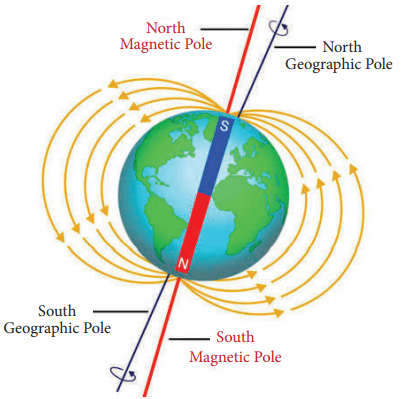
The Earth’s geomagnetic field has two main components: magnetic north and magnetic south. It’s important to note that these magnetic poles are distinct from the geographic poles, which are the points where Earth’s axis of rotation intersects its surface.
1. Magnetic North Pole:
The magnetic north pole is the point on the Earth’s surface where the geomagnetic field lines converge and point vertically downwards. As of my knowledge cutoff in 2022, the magnetic north pole was located in the Arctic region, specifically in the Canadian Arctic Archipelago, moving slowly over time.
The magnetic north pole is not fixed and undergoes gradual shifts due to complex processes in the Earth’s core. These shifts are monitored by geomagnetic observatories worldwide.
2. Magnetic South Pole:
The magnetic south pole is the point where geomagnetic field lines converge and point vertically upwards. Unlike the geographic south pole, which is in Antarctica, the magnetic south pole is not at a fixed location. As of my last update in 2022, it was located in the Southern Hemisphere, closer to the coast of Antarctica.
Similar to the magnetic north pole, the magnetic south pole also experiences gradual movements over time. The positions of both magnetic poles are subject to change due to the dynamic nature of the Earth’s geodynamo.
3. Geomagnetic Axis:
The geomagnetic axis is an imaginary line that connects the magnetic north and south poles. Unlike the Earth’s rotational axis, which defines the geographic poles, the geomagnetic axis does not align perfectly with the rotational axis.
The angle between the geomagnetic axis and the rotational axis is known as the magnetic inclination, and it varies depending on the location on Earth’s surface.
Understanding the locations and movements of the magnetic poles is essential for various applications, especially in navigation where magnetic compasses rely on the alignment with the geomagnetic field. It’s worth noting that the magnetic poles are not fixed points, and their positions can change over time due to the dynamic nature of the Earth’s molten iron outer core and the complex processes generating the geomagnetic field.
Geomagnetic pole vs Magnetic pole
The terms “geomagnetic pole” and “magnetic pole” are often used interchangeably, but they refer to different concepts in the context of Earth’s magnetic field. Let’s explore the distinctions between these two terms:
1. Geographic Poles:
The Earth’s geographic poles are the points where its axis of rotation intersects its surface. There are two geographic poles: the North Pole in the Arctic region and the South Pole in Antarctica. These poles are fixed points, and the Earth rotates around its axis, defining the planet’s north-south orientation.
2. Magnetic Poles:
Magnetic poles, on the other hand, are related to Earth’s magnetic field. There are two types of magnetic poles: magnetic north and magnetic south.
Magnetic North Pole: This is the point on the Earth’s surface where magnetic field lines converge and point vertically downward. It is distinct from the geographic North Pole and, as of my last knowledge update in 2022, was located in the Arctic region, specifically in the Canadian Arctic Archipelago.
Magnetic South Pole: This is the point where magnetic field lines converge and point vertically upward. Unlike the geographic South Pole, which is in Antarctica, the magnetic south pole is not fixed and, as of my last update, was located in the Southern Hemisphere, closer to the coast of Antarctica.
3. Geomagnetic Poles:
The term “geomagnetic poles” generally refers to the points on the Earth’s surface where the axis of a hypothetical dipole, which best fits the Earth’s magnetic field, intersects the Earth’s surface. These poles are theoretical constructs used for modeling purposes. There are two geomagnetic poles: the north geomagnetic pole and the south geomagnetic pole.
North Geomagnetic Pole: This is the point on the Earth’s surface where the axis of the best-fitting magnetic dipole intersects in the Northern Hemisphere.
South Geomagnetic Pole: This is the point where the axis of the best-fitting magnetic dipole intersects in the Southern Hemisphere.
4. Dynamic Nature:
It’s important to note that both magnetic poles and geomagnetic poles are not fixed points. They can undergo gradual shifts over time due to complex processes in the Earth’s core, particularly the movement of molten iron. These shifts are monitored by geomagnetic observatories worldwide.
Direction of Earth magnetic field
The Earth’s magnetic field has a general direction from its geographic South Pole to its geographic North Pole. This means that if you were to use a compass, the north-seeking pole of the compass needle would point towards the Earth’s magnetic north pole, which is located in the Arctic region. Conversely, the south-seeking pole of the compass needle would point towards the Earth’s magnetic south pole, which is located in the Southern Hemisphere, near Antarctica.
To put it simply:
The Earth’s magnetic field lines emerge from the magnetic south pole and converge towards the magnetic north pole.
The magnetic field lines are not perfectly aligned with the Earth’s rotational axis, leading to a difference between the geographic and magnetic poles.
It’s essential to note that the Earth’s magnetic field is not uniform, and there are local variations in its strength and direction. The magnetic field is influenced by the complex processes occurring in the Earth’s outer core, where molten iron generates electric currents, creating the geomagnetic field. Additionally, the magnetic field undergoes changes over time, including occasional reversals of its polarity, where the magnetic north and south poles switch places.
A magnet always attracts objects like iron, nickel, cobalt.
With the experiment with iron filling the can conclude that the Iron filling gets attracted near the ends of the magnets. These ends are called as Poles of a Magnet.
The attractive property is more at the poles.
Every magnet consists of two poles one is the north pole and other one south pole.
“The magnetic poles always exist in pairs” (Tamil Nadu Government #).
When a magnet is broken into two pieces, each piece behaves as a separate bar magnet.
When a magnet is vertically split, the length of the altered and each piece acts as a magnet.
When a magnet is horizontally split, the length of the new pieces of magnet remains unaltered and there is no change in their polarity.
In both cases, the strength of the magnet is reduced.
Repulsive Property
Like poles repel and unlike poles attract each other.
That is north pole attracts south pole and south pole attracts the north pole.
And North pole repels the north pole and south pole repels the south pole.
Directive Property
A suspended magnet always points towards the North-South Direction.
The freely suspended magnet always aligns itself to the North-South Direction and this property is called as the Directive property of magnet.
The north pole of the bar magnet always points towards the North and south pole of the bar magnet always points towards the south.
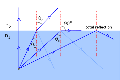
When the angle of incidence in the denser medium increases the angle of refraction also increases and it reaches a maximum value of r = 90° for a particular angle of incidence value. This angle of incidence is called the critical angle.
The angle of incidence at which the angle of refraction is 90° is called the critical angle.
When the angle of incidence exceeds the value of the critical angle, the refracted ray is not possible, since r > 90° the ray is totally reflected back to the same medium. This is called total internal reflection.
Condition for Total Internal Reflection
The LIght must travel from a denser medium to a rarer medium. Example: From Water to Air.
The angle of incidence inside the denser medium must be greater than than the critical angle. The angle of incidence inside the denser medium must be greater than the critical angle.
Total Internal Reflection in Nature
MIrage in the road deserts on Summer days.
Shining of Diamond.
Twinkling of stars
Total Internal Reflection Uses
Optical Fibre Communication(OFC) for transmitting audio and video signals. Optical fibers are used in medical, by physicians to look and work inside the body through tiny incisions without the need for surgery.
The rate of Light is 3 x 10⁶ m/s. The and the light’s in common glass is 2*10^8 m/s.
That is precisely 3,00000 km per second in a vacuum.
Speed of Light in Different Media
Light travels maximum in a vacuum and with different speeds in a different mediums.
Substance
Speed of light (ms-1)
Refractive Index (𝝁)
Water
2.25 x 10⁸
1.33
Glass
2 x 10⁸
1.5
Diamond
1.25 x 10⁸
2.41
Air
3 x 10⁸
1
Refractive Index and Speed of Light in different Medium
Note: The refractive index of a medium is also defined in terms of the speed of light in different media.
𝝁 = speed of light in vacuum or air (c ) / speed of light in a medium (v)
In general 𝝁 (Refractive Index) = speed of light in medium 1 / speed of light in medium 2
The speed of light in a vacuum is denoted as ‘c’. It is a universal constant.
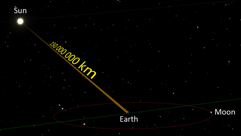
Sunlight travels in vacuum space and reaches earth after 8 minutes and 17 seconds. By LucasVB – Own work, Public Domain, https://commons.wikimedia.org/w/index.php?curid=20513669
Reason for the speed of light different in different mediums
The speed of light is decreased when travels through transparent media such as air, water, glass etc. The ratio by which the speed of light is decreased is called the refractive index of the medium and is always greater than one.
Which medium is light the fastest?
The light travels at maximum velocity in a vacuum. The vacuum has less refractive index than Air. Air has a refractive index of 1.003.
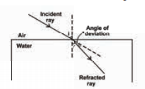
When the light is from one medium to medium with different optical densities, the path of light gets bent or deviated from the original path. This phenomenon is called the Refraction of Light.
Causes of Refraction of Light
Light rays get deviated from the original path when entering into another medium with different optical densities.
This deviation is due to a change of speed of light when entering into another medium.
This is because every medium has its unique optical density that affects the speed of light.
The velocity of light in low optical density or rarer medium is higher than the high optical density or denser medium.
Refraction of Light from a plane transparent Surface
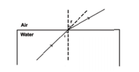
When the light goes from an optically rarer medium to a denser medium, it curves toward the normal.
Ray optic diagram for refraction of light
When the light goes from a denser to the rarer medium it turns away from the normal.
Light enters from air to water shows light is bending
A light incident normally on a denser medium goes without any divergence.
The Laws of Refraction of Light
The incident ray, the refracted ray, and the normal, all lie in the same plane.
“The ratio of the sine of the angle of incidence to the sine of the angle of refraction is a constant for a light of a given colour and for the given pair of media and this law is also called Snell’s law of refraction.” (Tamil Nadu Samacheer Kalvi #)
If i is the angle of incidence and r is the angle of refraction, then
Sin i / sin r = Constant.
This constant is called the refractive index of the second medium with respect to the first medium.
It is represented by 𝝁.
Note that the refractive index has no unit; it is the ratio of two similar quantities.
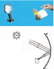
A concave mirror is used to focus the light rays to a single point which is used as a furnace. The above shows light is focused to burn a piece of paper
The parallel rays of light from the sun are focussed at a point using a concave mirror which is used to burn paper from the above diagram.
In the concave mirror, as we bring the object closer, the image gets bigger.
An Erected Magnified image is seen.
At some positions, there is no image that is obtained from the concave mirror.
There the conclusion is Concave is more complicated than the plane mirror.
Laws for the creation of Image made by Spherical Mirrors
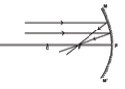
When the position of the object is at infinity, the position of the image is at the principal focus. The size of the image is point size and the nature of the image is real and inverted.
The position of the object is at infinity and the mirror is concave
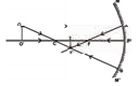
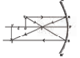
The position of the object is beyond the centre of curvature C where the position of the image formed is between F and C. The size of the image is smaller than the object and the nature of the image is real and inverted.
The position of the object is beyond the Centre of curvature C and the mirror is concave
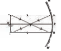
The position of the object is at the centre of curvature C then the position of the image is at C. The size is the same and the position of the image is real and inverted.
The position of the object is at Centre of curvature C and the mirror is concave
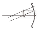
The position of the object is between C and F, then the position of the image is beyond C, the size of the image is Magnified and the nature of the image is real and inverted.
The position of the object is between C and F and the mirror is concave
The position of the object is at the principal focus F, then the image is formed at infinity. The size of the image is Infinitely large and the nature of the image is real and inverted.
The position of the object is at principal focus F and the mirror is concave
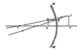
The position of the object is between the principal focus F and the pole P of the mirror. Then the image is formed behind the mirror. The size of the image is Magnified and the nature of the image is Virtual and Erect.
The position of the object is between the principal focus F and the mirror is concave
* * All the Notes in this blog, are referred from Tamil Nadu State Board Books and Samacheer Kalvi Books. Kindly check with the original Tamil Nadu state board books and Ncert Books.